picoでI2C bus scan
Page content
目的
I2C接続のOLEDディスプレイに表示をさせたい
そのためにまずは配線と認識できていることまでを実施する。
使用するOLEDは秋月電子の下記を利用する。
使用OLED : 0.96インチ 128×64ドット有機ELディスプレイ
参考 : ウィキペディア(I2C)
配線
I2CはGND/VCC/SCL/SDAの4本の配線を行えばよい。
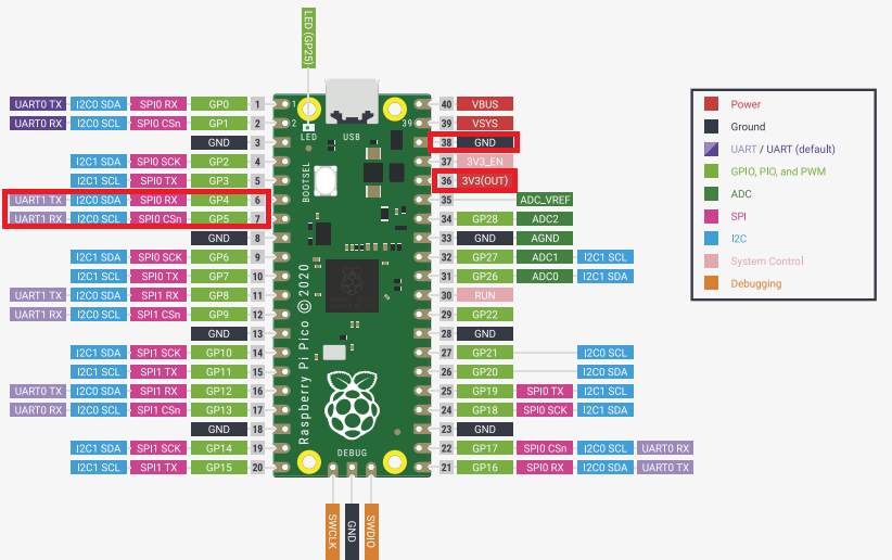
今回はpicoの赤で囲った部分をOLEDと配線する。

| pin番号 | 役割 |
|---|---|
| 6 | SDA |
| 7 | SCL |
| 36 | VCC(3.3V) |
| 38 | GNC |
サンプル調査
公式サンプルではI2Cのバススキャンサンプルは以下にある
pico-examples\i2c\bus_scan
このコードを見るとpicoでI2Cを使用するポイントは以下のようだ
- target_link_libraries
「hardware_i2c」を追加する - hファイル追加
#include “hardware/i2c.h”
#include “pico/binary_info.h”
I2Cの設定としては以下が必要なもよう
| API | 概要 |
|---|---|
| uint i2c_init (i2c_inst_t* i2c,uint baudrate) | I2Cの初期化、標準100kbit/s |
| void gpio_set_function ( uint gpio, enum gpio_function fn ) | pinの役割を設定する、今回はI2C用に設定 |
| static void gpio_pull_up ( uint gpio) | I2CのSDAとSCLをプルアップする |
| bi_decl | ? |
コード例
サンプルを参考に、すでに作成したex_02を拡張する。
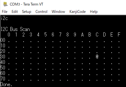
USBから「i2c」と入力することでサンプルのscanが実行されるようにする。
実行例

CMakeLists.txt
if (TARGET tinyusb_device)
    add_executable(ex_03
            ex_03.cpp
            )

    # Pull in our pico_stdlib which aggregates commonly used features
    target_link_libraries(ex_03 pico_stdlib hardware_i2c)

    # enable usb output, disable uart output
    pico_enable_stdio_usb(ex_03 1)
    pico_enable_stdio_uart(ex_03 0)

    # create map/bin/hex/uf2 file etc.
    pico_add_extra_outputs(ex_03)

    # add url via pico_set_program_url
    example_auto_set_url(ex_03)
elseif(PICO_ON_DEVICE)
    message(WARNING "not building ex_03 because TinyUSB submodule is not initialized in the SDK")
endif()
ex_03.cpp
/**
 * the reserved_addr(uint8_t addr) function is:
 * the i2c_bus_scan() function is:
 *          Copyright (c) 2020 Raspberry Pi (Trading) Ltd.
 *          SPDX-License-Identifier: BSD-3-Clause
 */

#include <stdio.h>
#include "pico/stdlib.h"
#include "hardware/i2c.h"
#include "pico/binary_info.h"
#include "class/cdc/cdc_device.h"


// I2C reserves some addresses for special purposes. We exclude these from the scan.
// These are any addresses of the form 000 0xxx or 111 1xxx
bool reserved_addr(uint8_t addr) {
    return (addr & 0x78) == 0 || (addr & 0x78) == 0x78;
}

int i2c_bus_scan(){
    printf("\nI2C Bus Scan\n");
    printf("   0  1  2  3  4  5  6  7  8  9  A  B  C  D  E  F\n");

    for (int addr = 0; addr < (1 << 7); ++addr) {
        if (addr % 16 == 0) {
            printf("%02x ", addr);
        }

        // Perform a 1-byte dummy read from the probe address. If a slave
        // acknowledges this address, the function returns the number of bytes
        // transferred. If the address byte is ignored, the function returns
        // -1.

        // Skip over any reserved addresses.
        int ret;
        uint8_t rxdata;
        if (reserved_addr(addr))
            ret = PICO_ERROR_GENERIC;
        else
            ret = i2c_read_blocking(i2c_default, addr, &rxdata, 1, false);

        printf(ret < 0 ? "." : "@");
        printf(addr % 16 == 15 ? "\n" : "  ");
    }
    printf("Done.\n");

    return 0;
}


int main() {
    stdio_init_all();

    unsigned short cmd_buff_index_ = 0;
    char cmd_buff[256] = {0};
    char tmp_input;
    int res = 0;

    // i2c setting
    // This example will use I2C0 on the default SDA and SCL pins (4, 5 on a Pico)
    i2c_init(i2c_default, 100 * 1000);
    gpio_set_function(PICO_DEFAULT_I2C_SDA_PIN, GPIO_FUNC_I2C);
    gpio_set_function(PICO_DEFAULT_I2C_SCL_PIN, GPIO_FUNC_I2C);
    gpio_pull_up(PICO_DEFAULT_I2C_SDA_PIN);
    gpio_pull_up(PICO_DEFAULT_I2C_SCL_PIN);
    // Make the I2C pins available to picotool
    bi_decl(bi_2pins_with_func(PICO_DEFAULT_I2C_SDA_PIN, PICO_DEFAULT_I2C_SCL_PIN, GPIO_FUNC_I2C));

    // led setting
    const uint LED_PIN = PICO_DEFAULT_LED_PIN;
    gpio_init(LED_PIN);
    gpio_set_dir(LED_PIN, GPIO_OUT);

    while (true) {
        // RxBuffにデータが存在する
        if(tud_cdc_available() > 0){
            // 1文字受信
            tmp_input = tud_cdc_read_char();

            // 改行文字か?
            if(tmp_input == '\r') {
                // 表示改行
                printf("\n");
                // null文字付与
                cmd_buff[cmd_buff_index_] = '\0';
                // コマンド判断
                char* command = &cmd_buff[0];
                if(strcmp(command, "led") == 0) {
                    printf("LED Blink\n");
                    gpio_put(LED_PIN, 1);
                    sleep_ms(250);
                    gpio_put(LED_PIN, 0);
                    sleep_ms(250);
                } else if(strcmp(command, "i2c") == 0) {
                    if(i2c_bus_scan() != 0) printf("is2 bus scan err\n");
                } else {
                    printf("no such command\n");
                }
                // index clear
                cmd_buff_index_ = 0;
            } else {
                cmd_buff[cmd_buff_index_] = tmp_input;
                cmd_buff_index_++;
            }
        }
        // wait
        sleep_ms(1);
    }
}
